5 steps to keep your chips under control
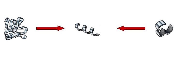
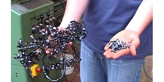
Good chip formation, leading to a spirally shaped chip, guarantees good tool life, easy handling and evacuation of chips, a stable and reliable cutting process, good quality and surface roughness of the machined surface and an efficient process. In short, a good chip must have good sized portions that are easy to handle and that doesn’t take too much of an effort to generate.Good chip formation produces spiral-shaped chips and guarantees good tool life, easy chip handling and evacuation, good surface quality and a stable, reliable, efficient cutting process. In short, a good chip must be an easy-to-handle size and require minimal effort to generate.
| Tool | Cutting conditions | Material | Coolant |
Rake angle Cutting Edge angle Nose radius Coating Cutting edge and chipbreaker
geometry | Feed Cutting depth Chip thickness ratio Cutting speed | Hardness Tensile strength Ductility Structure | Dry machining Emulsion cooling Seco Jetstream |
Various groups of factors offer practical ways to influence chip formation, including cutting tools, cutting conditions, materials and cooling system.
Material factors include workpiece hardness and tensile strength, ductility and structural considerations. These elements cannot be modified to improve chip formation, but the machinist must consider their impact on chip formation.
The influence of cooling system on chip formation is rather arbitrary. It is very difficult to see fixed relationships between the type of cooling system and its impact on chip formation. One exception is the so-called HPDC (High Pressurized Directed Cooling) system, which clearly leads to much-shorter chips. This type of cooling system is applied in the Seco Jetstream tooling system.
The impact of tool features on chip formation is a frequent topic of discussion. Of main importance here are the rake angle and cutting-edge angle, nose radius, and the geometry of the cutting edge and chip breaker. Larger rake angles, lower cutting-edge angles and a larger nose radius yield longer chips. The impact of the coating type on chip formation is not clearly definable.
The most practical way to influence chip formation is to modify cutting conditions, which can be very easy and effective to change. The basic cutting condition to adjust is chip thickness ratio or slenderness. When chip thickness ratio is too small, it produces so-called square chips that create overly high loads on the tool nose and thus limit tool life considerably. A too-high chip thickness ratio leads to slender ribbon-shaped chips that are very difficult to break into short pieces.
Chip thickness ratio is defined as the width of cut divided by the thickness of the chip. The depth of cut for a given feed should be large enough to avoid a too-small or too-large chip thickness ratio. Small depths of cut combined with certain feeds produce square chips. Overly small feeds can lead to ribbon-shaped chips that are unbreakable.
In practice, depth of cut often is a given. In this situation, the feed forms the key to good chip formation. Avoid both overly low feeds that lead to long ribbon-shaped chips and overly high feeds that create square chips.
The more-complex influence of cutting speed on chip formation will be discussed in greater detail later in this chapter.
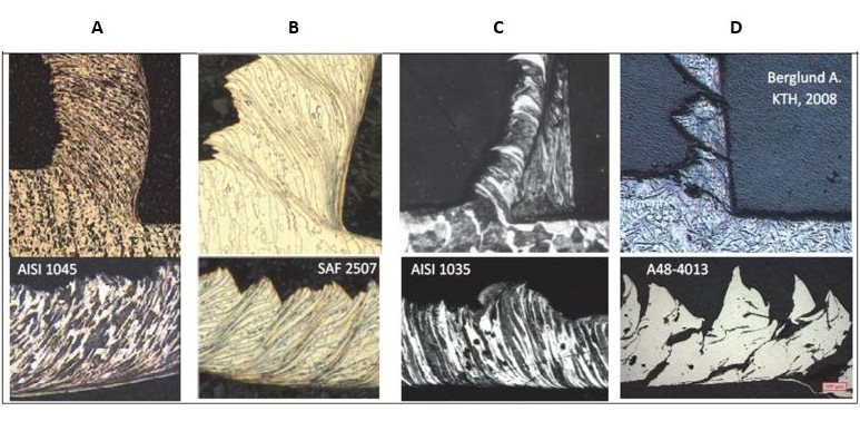
Actual cross section defines four different types of chips:
- Serrated, segmented or noncontinuous chips
- Continuous chips with narrow, straight, primary shear zones, or continuous chips with a secondary shear zone at the toolchip interface
- Builtup edge chips
- Shearing chips or short chips
All chips have two surfaces. The outer surface displays a shiny, polished surface because it rubs – and causes wear – on the rake face of the tool. Every chip also has an inner surface formed by the original surface of the workpiece, with a jagged, rough appearance caused by the actual shearing mechanism.
| Segmented chip | Continous chip | Chip with
built-up edge | Shearing chip |

Serrated or segmented chips – also called non-continuous chips – are semi-continuous chips with large zones of low shear strain and small zones of high shear strain or shear localization. These types of chips appear when machining materials with low thermal conductivity and high strain-hardening tendencies. The material strength increases when the stress in the material increases, especially in combination with a higher temperature, as is the case with titanium. These chips display a saw-tooth appearance.
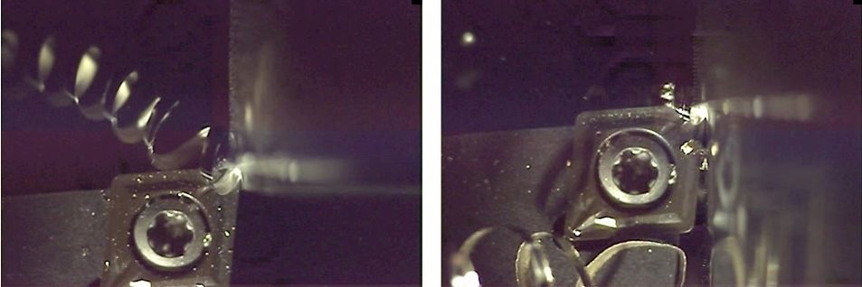
Continuous chips form when machining ductile materials, including mild steel, copper and aluminum. The plastic deformation of ductile material produces long, continuous chips, desirable from the perspective of cutting action because it produces good surface roughness with low power consumption and longer tool life. Continuous chips often form with a small chip thickness, high cutting speed, sharp cutting edge, large rake angle on the cutting tool, smooth tool face and an efficient lubricating system. These chips are difficult to handle and evacuate. They can coil in a very long spiral or helix shape that curls around the workpiece and tool and may injure the operator when the chip breaks. The tool face is in contact for a longer period, which produces more frictional heat. Chip breakers can rectify this problem.
Deformation takes place along a narrow shear zone called the primary shear zone. Some continuous chips may develop a secondary shear zone at the tool/chip interface. This zone becomes thicker as friction increases. Continuous chips also may occur with a wide primary shear zone that displays curved boundaries. The lower boundary of the deformation zone – the side flow effect – can drop below the machined surface, which distorts the surface and leads to a poor surface finish.
A built-up edge forms when small particles of workpiece material stick to the cutting edge. This occurs mainly with soft and ductile workpiece materials and when continuous chips form. A built-up edge may affect the cutting action of a tool. This built-up material is extremely hard and brittle, and becomes unstable as successive layers add to it. When a built-up edge breaks off, part of it is carried up the face of the tool along with the chip while the remainder is left in the machined surface. This latter part roughens the machined surface.
Increased cutting speeds and rake angle, sharper tools, use of coolant and of a cutting material with lower chemical affinity for the workpiece material can reduce the formation of built-up edge.
Figure 9: Examples of built-up edges and chips for different cutting speeds.
Shearing chips or short chips – also called discontinuous chips – consist of segments that are detached from each other. These chips form when cutting brittle workpiece materials such as bronze, hard brass and gray cast iron, as well as very hard materials or those with hard inclusions and impurities. Brittle materials lack the ductility necessary for appreciable plastic chip deformation. Repeated fracturing limits the amount of chip deformation.
Discontinuous chips are produced in brittle workpiece materials under conditions that include large chip thicknesses, low cutting speeds and small rake angles. On machine tools with low stability, short chips can lead to micro vibrations during the operation because of intermittent chip formation. These types of chips offer one advantage: convenient handling and disposal. Formation of these chips in brittle materials produces fairly good surface finish, consumes less power and yields reasonable tool life. With ductile materials, however, discontinuous chips produce poor surface finishes and excessive tool wear.
A. Carbon steel with continuous chip
B. Duplex stainless steel with segmented chip
C. Carbon steel with a built-up edge
D. Cast iron with discontinuous chips
Long and continuous chips tend to have a negative effect on machining efficiency, with a risk of damage to the cutting tool, workpiece and machine tool. They can lead to unnecessary production stoppages because of chip-evacuation problems and create unsafe work conditions for the operator. These chips should be broken into small pieces for safety, easy removal and prevention of damage to the machine tool and workpiece.
Chips develop a curvature or curl during formation based on factors that include the following:
- distribution of stresses in the primary and secondary shear zones
- thermal effects
- strain-hardening characteristics of the workpiece material
- cutting tool geometry
- to some extent, the cooling system
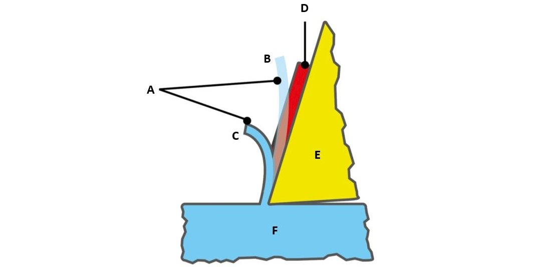
In general terms, when the rake angle decreases (negative tooling), chip curvature becomes tighter, which leads to shorter, broken chips. Chip breakers serve to reduce the radius of chip curvature and thus break chips into shorter lengths.
A. Chip
B. Without chip breaker
C. With chip breaker
D. Chip breaker
E. Tool
F. Workpiece
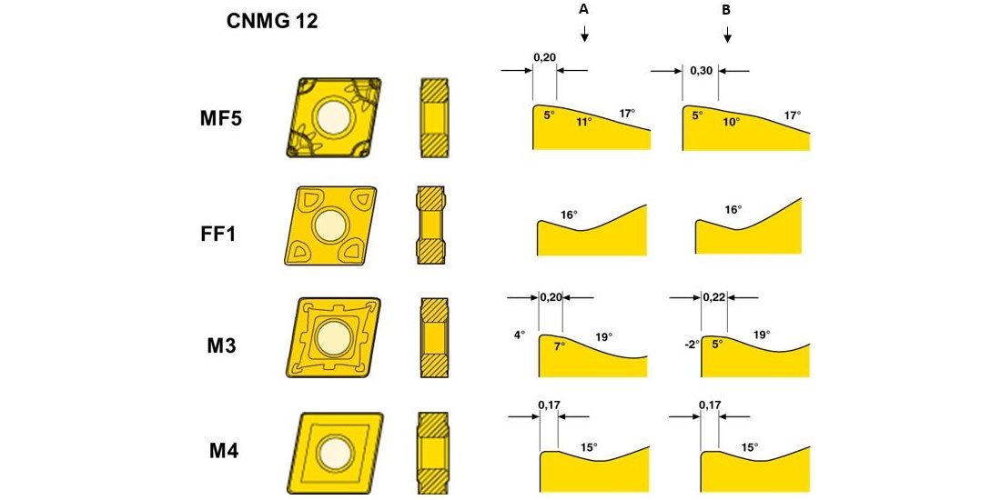
Select chip-breaking geometries based on the type of operation, the combination of feed and depth of cut, and the type of workpiece material.
A. Corner
B. Cutting edge
A chip-breaking diagram (see Figure 14) can show the relationship among workpiece material, cutting conditions, chip-breaking geometry and chip formation. This diagram identifies the considerations involved in selecting depth of cut and feed to machine a specific workpiece material with a defined chip-breaking geometry. The horizontal axis represents the feed, which always must be larger than a certain minimum (the width of the T-land geometry) and should remain lower than a certain maximum (never larger than half the nose radius). The vertical axis shows the depth of cut, which always should be larger than the nose radius to promote good chip formation and avoid problems with square chips. Additionally, the depth of cut never should be larger than the cutting edge length. In the latter case, it is advisable to work with safety factors, which depend on the strength of the cutting edge. In the case of inserts, these safety factors vary between 75% (for square or rhombic inserts) and 20% (for copy inserts with a small top angle) of the cutting edge length.
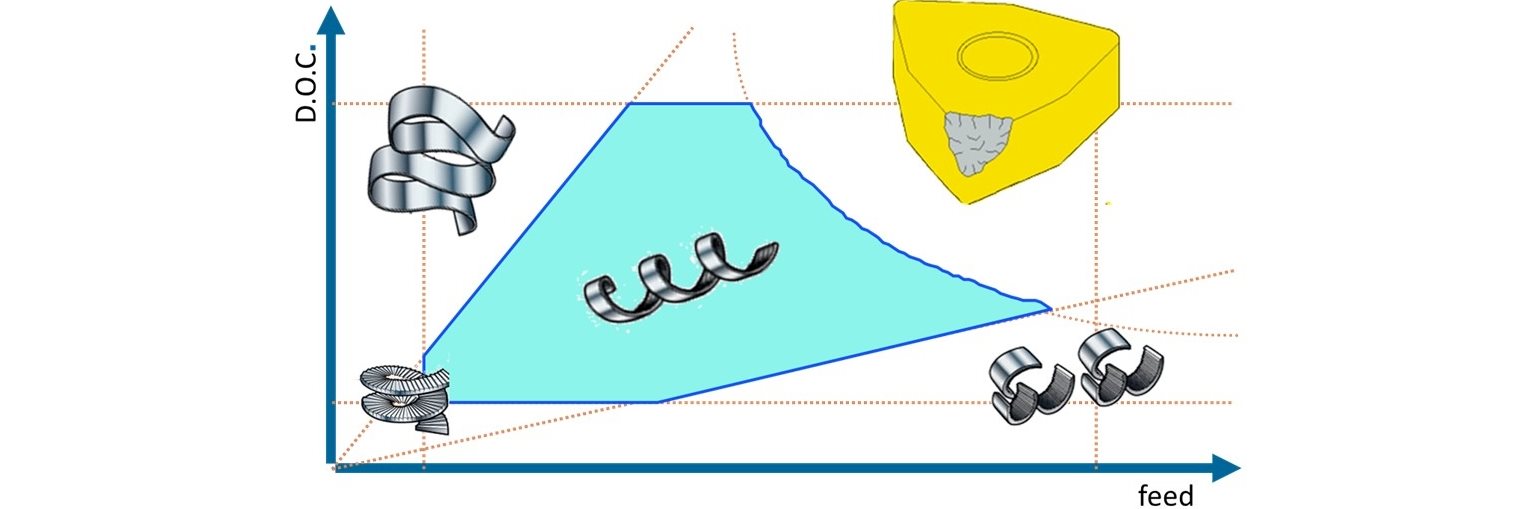
Together, both depth of cut and feed – the so-called chip thickness ratio – must remain between certain constraints. The maximum chip thickness ratio should remain below a certain maximum value to avoid too-long ribbon-shaped chips. The chip thickness ratio also should remain above a minimum value to avoid square chips. Figure 14 represents these constraints with two angled lines. The minimum and maximum value of the chip thickness ratio depends on workpiece material. To minimize broken cutting edges, the cutting forces should not rise too high. Figure 14 shows this constraint as a curved line.
Every combination of feed and depth of cut in the blue zone in Figure 14 will produce correctly shaped chips. In a combination selected outside this blue zone, the cutting edge and chip breaking geometry will not function well. Chips will be too long or too square, or the cutting-edge breakage will exceed an acceptable amount.

Figure 15 illustrates the influence of cutting speed on chip formation. The horizontal axis of the graph shows the feed and the vertical axis represents types of chips. In general, as feeds increase, chips tend to become shorter, especially at low cutting speeds. As cutting speed increases, however, the relationship between feed and chip formation chip becomes lower.
ISO material group use, negative basic shape inserts
 | Stainless steel (ISO M) Superalloys (ISO S) |  | Steel (ISO P) Stainless steel (ISO M) Superalloys (ISO S) |  | Stainless steel (ISO M) |
 | Steel (ISO P) Stainless steel (ISO M) Hardened steel (ISO H) |  | Superalloys (ISO S) |  | Steel (ISO P) Stainless steel (ISO M) Cast iron (ISO K) |
 | Steel (ISO P) Cast iron (ISO K) |  | Cast iron (ISO K) |  | Steel (ISO P) |

A chip breaking diagram such as Figure 16 provides a graphical representation that relates different types of chip breaking geometries and their applications to each other. This diagram ranks different chip breaking geometries (named FF1, FF2, MF1 … RR97) relative to their cutting-edge strength and application. The horizontal axis represents the relative cutting edge strength of the geometry. To some extent, it also indicates the feeds suitable for certain geometries.
The vertical axis represents the type of application, ranging from finishing (small depths of cut) to roughing (large depths of cut). To some extent, the vertical axis represents relative depths of cut suitable for certain geometries. The actual size of the insert – the cutting-edge length – also influences the effective depth of cut. The various ISO-defined colors indicate which workpiece materials suit these geometries.
A geometry positioned at the lower left of this diagram is very sharp and generates short chips, but it also offers low cutting-edge strength that requires equally low cutting conditions (depths of cut and feeds). Conversely, geometries at the top right of the diagram have strong cutting edges and can be used with high cutting conditions, but they tend to form long chips.
- Prioritize the process-optimization criterion: either productivity or cost efficiency.
- If chip formation is acceptable, go to step 5.
If chips are too long, go to step 3.
If chips are too short, go to step 4. - If productivity is important, increase the feed.
If cost efficiency is important, change the chip breaker to a stronger geometry.
Keep the feed within the range of the chip-breaking geometry.
Go to step 5. - If productivity is important, change the chip breaker to a sharper geometry.
If cost efficiency is important, reduce the feed.
Keep the feed within the range of the chip-breaking geometry.
Go to step 5. - If cost efficiency is a priority, lower cutting speeds to improve it.
If productivity is a priority, increase cutting speeds to improve it.
Inline Content - Survey
Current code - 5fce8e61489f3034e74adc64