Tool Geometries Make the Machining Difference
What tools are made from is important, but it’s their geometries that determine what can be achieved application-wise.
A shop can have all the essential elements of a machining process – the right machine tool capabilities, proper tool holding and part clamping, and ... – in place, but if it has selected the wrong tool geometry for the application, achieving optimized part production is unobtainable. Tool geometries are critical because they directly impact tool life, chip control, edge stability and micro cutting characteristics, all of which, in turn, affect overall machining costs.
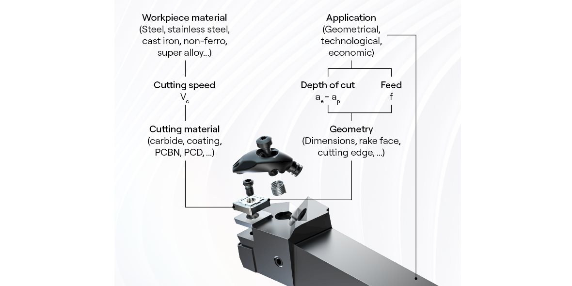
The selection of cutting tools is based primarily on the workpiece material that needs to be machined. But workpiece material properties and cutting tools features need to work together. The two must have a connection, and that is defined by cutting conditions such as speeds, feeds, and depths of cut. Cutting speed is the connection between workpiece material and cutting material, while depths of cut and feeds connect tool geometry with the application type and to some also extend the workpiece material.
A tool’s form and shape, and dimensions are its geometry and determining that geometry involves several elements.
One element is the cutting-edge line’s slope, shape, and dimension. The longer the cutting edge, the deeper the depth of cut that can be used. Cutting edge lines are longer for roughing geometries and shorter for finishing operations. Another aspect of the cutting-edge geometry is its appearance on a microscale. At that level, cutting edge lines are straight or curved, positioned flat or tilted and are ‘’thick or thin’’.
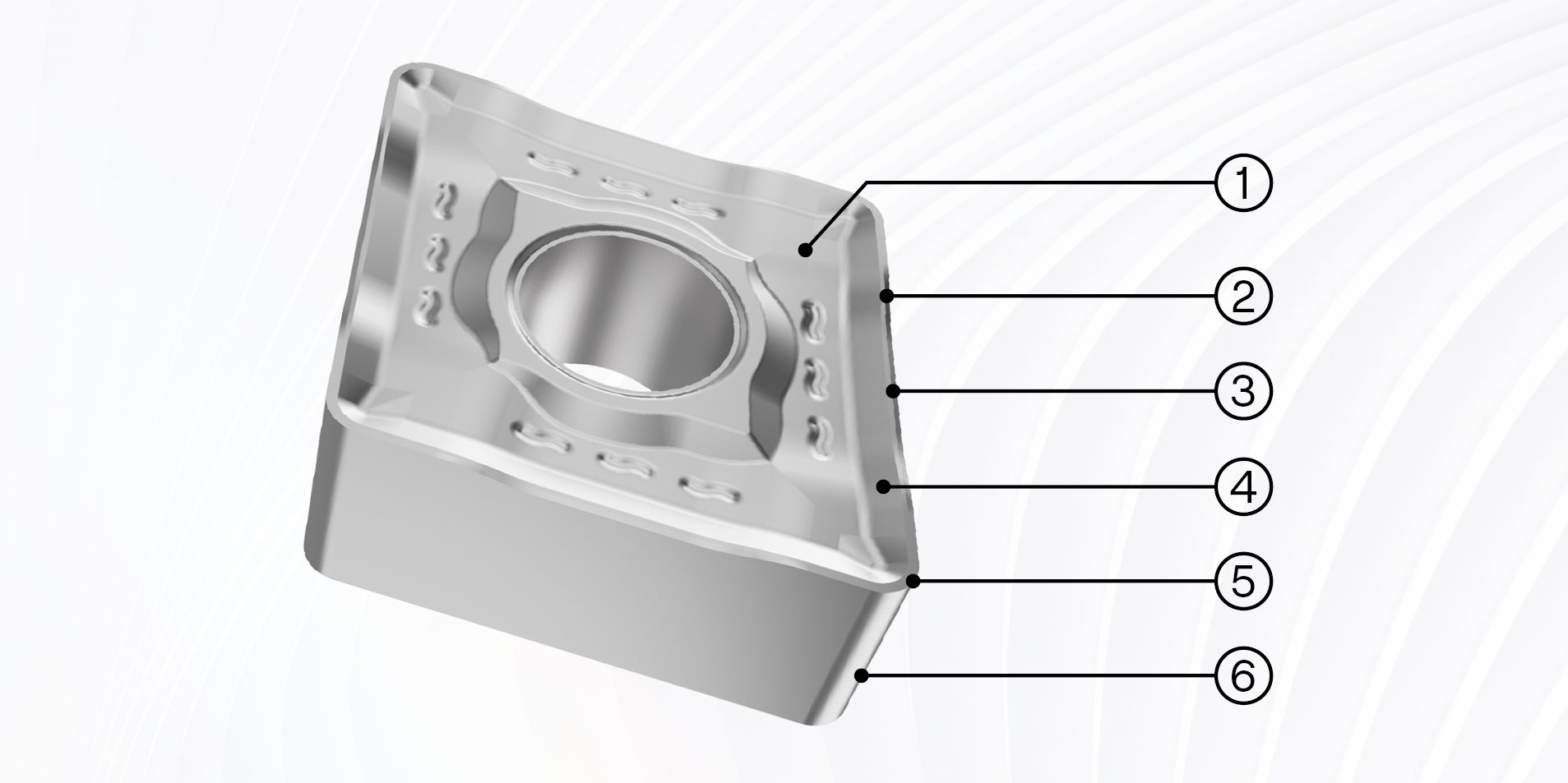
The other elements of geometry are the rake face, cutting point, clearance face and transition (T)-land. The rake face positioning geometry is one of the two plains that cross to form the cutting-edge line. It is the part of the tool where the chip, as it is formed, will glide over, and be evacuated, while the cutting point type, position and geometry is where the main cutting edge ends in the operation – on the level of the machined surface essentially. The clearance face position geometry is the second of the two plains that cross to form the cutting-edge line. The clearance face position serves a dual purpose: making the penetration of the cutting edge in the workpiece materials possible and offer stability to the cutting edge.
In between the rake face and cutting-edge line is the T-land. On PCBN and ceramics tools, the proper T-land geometry can be the difference between success and failure. Using inserts made from those cutting materials but combined with the wrong T-land geometry will destroy the tool in a matter of seconds.
In actual machining, there are also three distinctions when it comes to cutting edge geometry. Those are the nominal, true and effective geometry.
The nominal cutting edge geometry is the unified rake face geometry of a cutting tool (with flat rake face) in reference to the cutting-edge positioning. Those positions are negative, neutral, and positive cutting-edge positioning.
- Positive cutting-edge geometries are recommended for workpiece materials with higher ductility and adhesive tendency and operations involving lower feeds and depths of cut (finishing) in favourable cutting conditions.
- Negative cutting-edge geometries are well suited for materials with higher hardness and abrasiveness tendencies and operations with higher feeds and depths of cut (roughing) in unfavourable cutting conditions.
- Neutral cutting geometries are advised for when the shape of the cutting edge needs to be projected precisely on the machined surface as with threading, form profiling and other such operations.
A modern cutting tool has a true cutting geometry, which is a composition of its non-flat rake face geometry (chip breaking geometry), cutting-edge geometry (cutting edge treatment) and its T-land geometry. However, if cutting conditions and cutting data for the tool are unknown, nothing can be said about the true cutting geometry because it is not a given fact but will depend on how the tool is used.

The effective geometry of a cutting tool is a ‘’virtual’’ geometry determining how the cutting edge will function during the machining process. This behaviour is influenced by the cutting conditions – heavy duty machining, hard machining, micro machining, ect. – and the actual cutting data during the process.
Inline Content - Gridded Links
Tags: 'geometry_factor'
Max links: 1
The tool itself – material, form, and shape – and how its cutting edge is positioned all play a role in effective tool performance. A good tool geometry will yield poor results if it isn’t used properly, and the same can be said about the wrong tool geometry used properly. If the geometry is wrong, the machining operation suffers from the beginning.
To differentiate between theory and practice, geometry is referred to as how a cutting edge looks, how big it is, its radius, type of chamfer, etc. But what is equally, if not more, important is how that cutting edge is positioned, meaning in what orientation is it being held in relation to the cutting movement.
Cutting edge positioning is all about strength and stability. To accurately position a cutting edge, shops must know the tool’s material, complexity (one edge, two edge) and its geometry because optimum positioning/tool clamping will vary depending on those factors.
A cutting edge is connected to a tool and the tool is connected to the machine tool. That connection must be accurate, strong, and stable. A shop could have the right cutter geometry and have its cutting edge positioned correctly in a holder, but if that holder has excessive runout, the whole machining process will fail.
Each feature of a tool geometry serves a purpose, whether for tool life, chip control or edge stability. These features include the shape and dimensions of an insert; the cutting-edge length; primary and secondary cutting edges; the position and geometry of the cutting point; the edge line, rake and clearance face position; cutting edge angle; rake face geometry; and micro cutting-edge geometry.

- Global Shape and dimensions of cutting edge carrier
- Cutting edge line type and position
- Cutting edge geometry
- Rake face position
- Cutting point type and geometry
- Clearance face position geometry
- The global shape of an insert as it is defined by its rake face, clearance face and point have a big impact on the strength of a tool. The larger the point angle of the cutting tool, the higher the tool’s overall resistance to breakage.
- The length of the cutting edge determines the maximum depth of cut the tool can handle.
- The primary cutting edge of a cutting tool performs the actual machining. That edge ends at the cutting point, and when it extends beyond that, it is referred to as the secondary cutting edge – also called the scraper or wiper cutting edge. The secondary cutting edge along with point geometry and feeds significantly influence workpiece surface finish quality.
- The strength of the cutting point enables higher cutting conditions. Stronger points allow for bigger depths of cut and higher feeds.
- Edge line, rake and clearance face position give a cutting-edge line its positioning. This is called the inclination angle (or helix angle), and it encompasses how the cutting-edge angle is orientated as compared to the cutting direction. This geometrical element is used to influence chip formation – for reliability of the process – and cutting pressure – for tool life.
- The cutting-edge angle also defines how cutting edges are positioned. The lead angle or cutting-edge angle is the positioning of a cutting edge compared to the feed used with the tool.
- The rake face geometry influences how chips are formed and evacuated. In this respect, there are sharp, medium, and strong geometries, which refer to the application. A fine or sharp geometry is for finishing, medium geometry for the average operation and a strong geometry is for roughing applications.
- The micro cutting-edge geometry is very small, and changes during machining due to wear appearing on the cutting-edge line.
In addition to determining the different attributes of cutting geometry, understanding how it influences the cutting process, or the “nature” of the geometry versus its performance, is equally as critical in selecting the right tool. Additionally, it should be noted that the two can differ.
The behavior of a geometry is dependent on the cutting conditions in which the tool is used. From one set of conditions to the next, a tool’s behavior and performance will vary even though its geometry has not changed. Among these cutting conditions are neutral cutting geometries, positive cutting geometries, and negative cutting geometries.
Neutral cutting geometry means that the effective rake is zero degrees and the angle between the cutting direction and the cutting rake is 90 degrees. There is a balance between the tool with a certain amount of strength and the cutting process itself that puts machining loads on the cutting edge.
Positive cutting geometry is when the angle between the cutting direction and the cutting rake is larger than 90 degrees, thus creating a positive effective rake. This means the new balance point involves the loads acting on the tool are lower, but the ability for the tool to withstand the loads is also reduced. Positive cutting is effective for easy cutting applications or situations where the loads acting on a cutting tool are lower as with shallower depths of cut and lower feeds.
Negative cutting processes occur when the angle between the cutting direction and the cutting rake is less than 90 degrees. This application is used when high loads acting on the cutting edge are expected.
While what tools are made from is important, it’s their shapes, or geometries, that determine what is possible from an application perspective. Determining a good functioning tool for machining is two things: one is that the combination of cutting tool material and workpiece material needs to be in balance, and the balancing element is the cutting speed.

The second is that the application and cutting geometry must also be in balance. It is for this second reason that shops must have a knowledge of cutting-edge geometries and how they make all the difference in optimizing machining processes.
Inline Content - Survey
Current code - 5fce8e61489f3034e74adc64